Instructions for using tapered taps for pipes
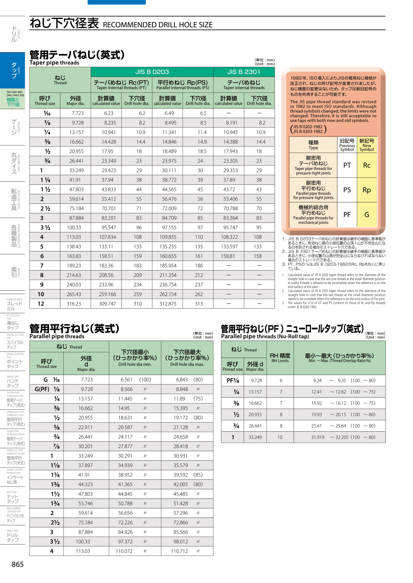
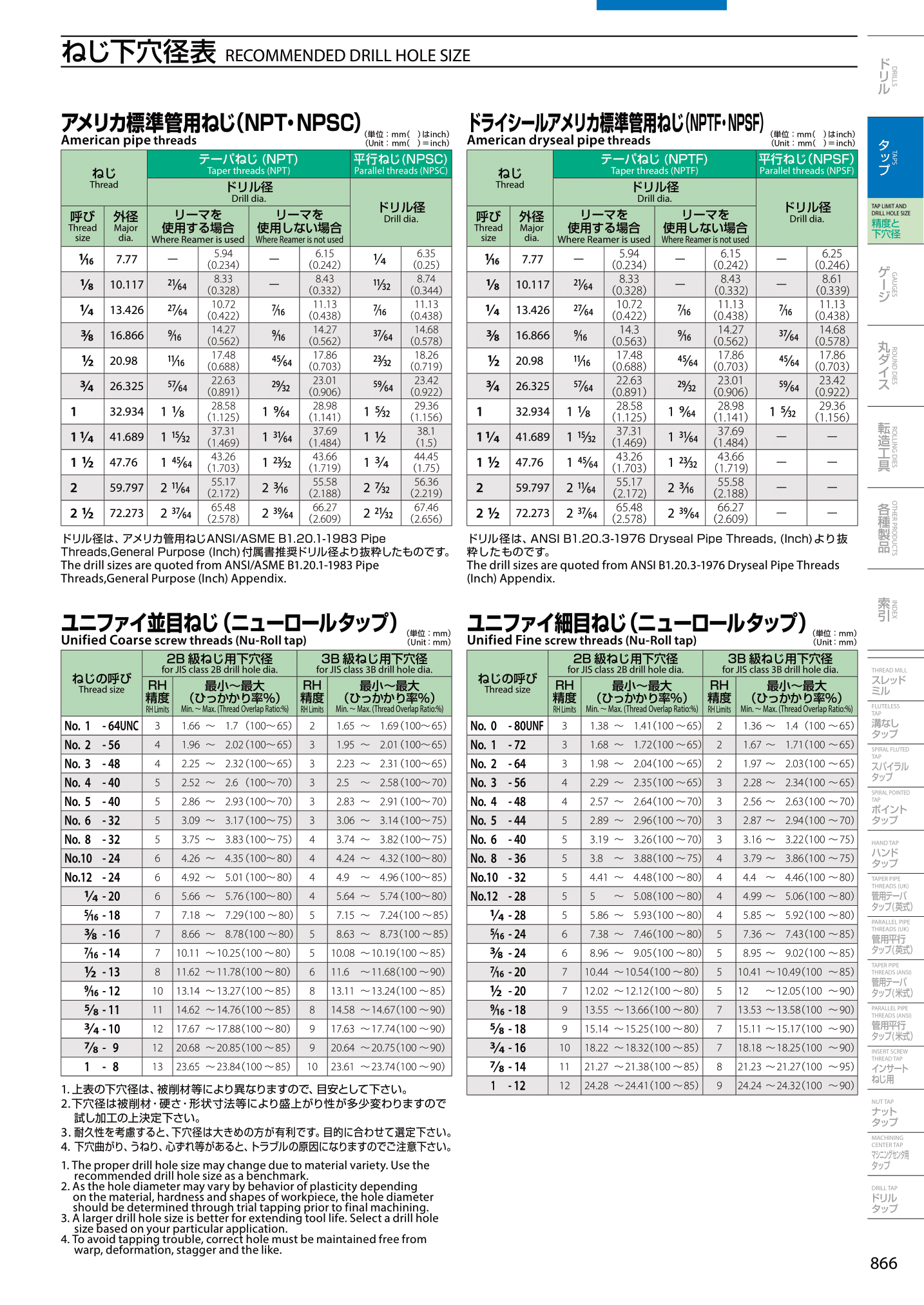
(1) Drill a pilot hole with the diameter set for each call.
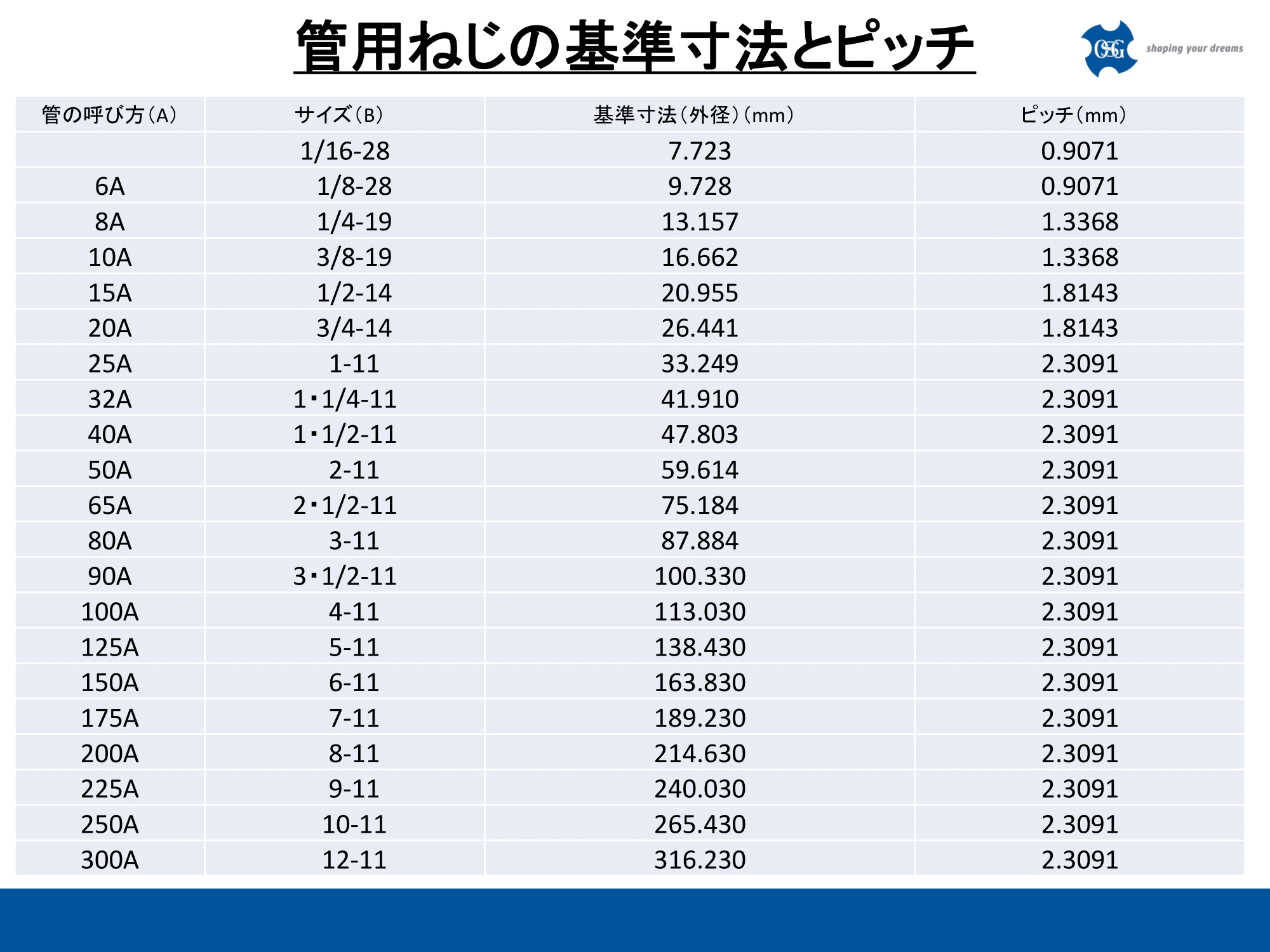
In addition to fractions such as 3/8 and 1/2, pipe screws may be expressed as 10A and 15A. Please refer to the link below to check the name of the screw.
* Please refer to the column of pipe screws.
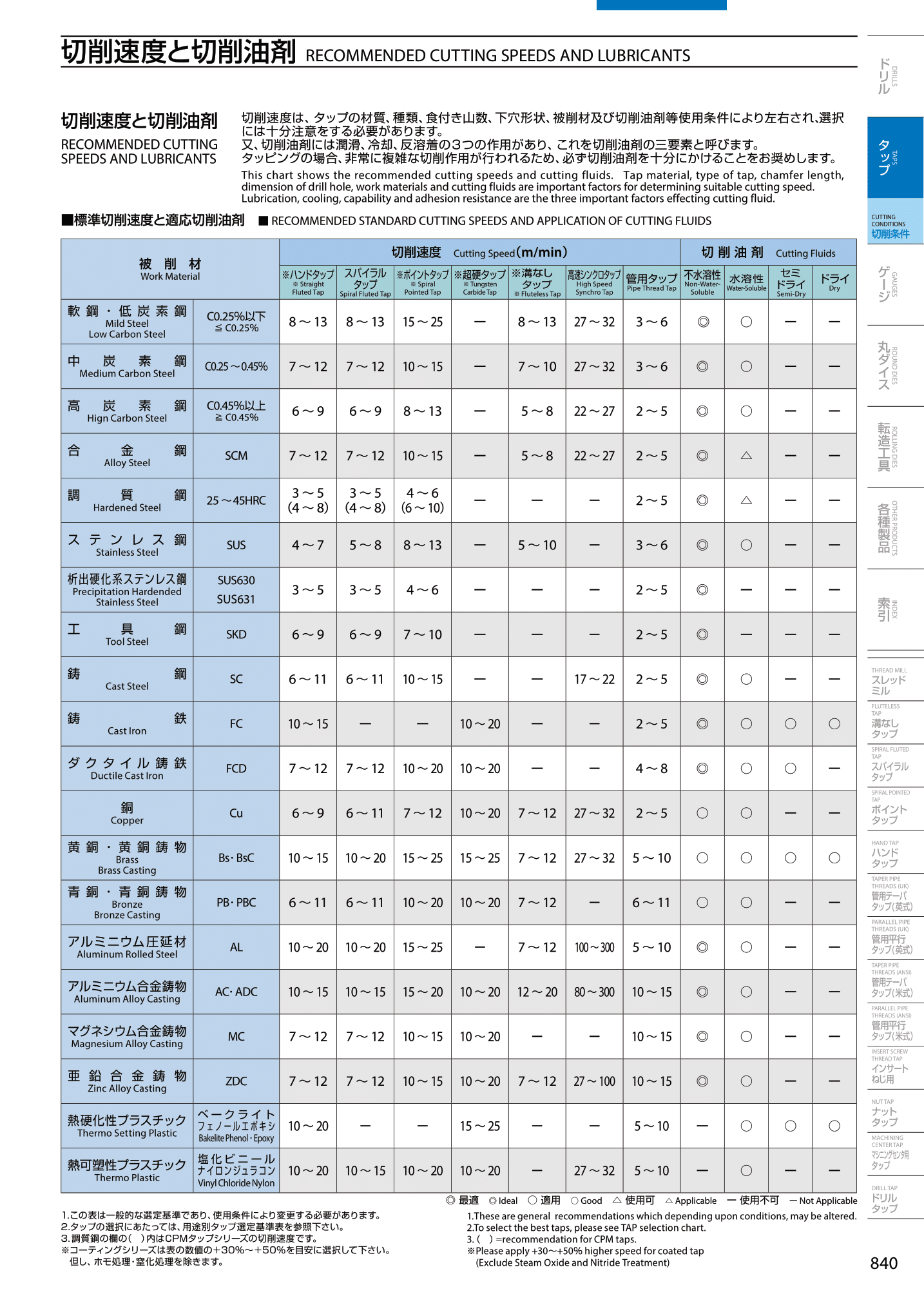
(2) Set the cutting conditions of the tapered tap for the tube.
* The tool diameter of the tap for pipe screws (both parallel and tapered) cannot be calculated by calculation like unified screws. From the pilot hole table above, calculate the outer diameter of the screw indicated in the screw name as the tool diameter. In addition, in the case of American standard pipe screws, the outer diameter of the tool is different from that of the English PT and Rc. Please check from the preliminary hole table above.
The rotation speed (min-1) (=S) is calculated from the above tap tool diameter and the cutting speed within the range of each workpiece material.
Spindle rotation speed [min-1]
= Vc (cutting speed) × 1000 ÷ DC (tool diameter) ÷ 3.14
Reference: Tap Condition Criteria Table
Since the feed speed (= F) of the tap is 1 revolution and 1 pitch, the value obtained by multiplying the pitch of the above material by the rotation speed is calculated (mm / min). You have now calculated the rotational speed and feed rate at which the tool is moving.
(3) Process the tap to the depth (reference diameter position) set for the tap.
In the OSG catalog, there is a description of the reference diameter position (mm) for each tap used.
* There is also a tolerance for the reference diameter position, so when using a new tapered tap for pipes, lower it shallowly to find a depth that allows the gauge to pass.(4) Pull out the tap with reverse rotation.
(5) Inspect using the gauge indicated in the drawing.


(6) If the gauge inspection passes, it is completed.
• Instructions for using tapered taps for pipes

・ (American standard pipe screws: NPT, NPTF, etc.) Screw pilot hole table for pipes

• Reference dimensions and pitch of pipe screws

・ Tap Condition Criteria Table
