Learn how to calculate cutting data for helical machining on end mills and indexable ( chip exchangeable) cutters.
As an example, let's consider the case of helical machining of a φ18 hole with a ramping angle of 3° with a carbide anti-vibration type end mill AE-VMSS φ10.
The recommended conditions in the catalogue are a rotation speed of 3,200 min-1 and a feed rate of 840 mm/min.
(1) Calculate the approximate basis based on the recommended conditions for groove processing in the catalog.
The rotation speed and feed amount per revolution are estimated to be ×70% of the grooving conditions recommended by the catalog.
Rotation speed (approximate) = 3,200 × 0.7 = 2,240 min-1
Feed amount per revolution (approximate) = (840÷3,200) × 0.7 = 0.18375mm/rev
(2) Correction of feed rate from machining diameter and tool diameter
The feed rate "F" of the machine is the "moving speed of the tool center".
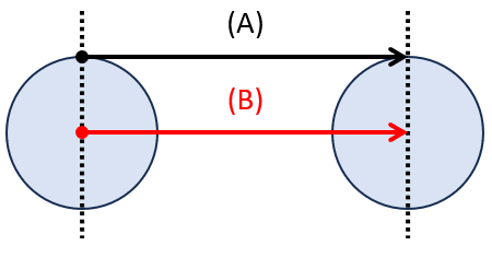
If the tool is moved in one direction, the "distance traveled around the center of the tool" and the "distance traveled around the perimeter of the tool" are the same.
The numerical values in the catalog condition table are expressed in this way of thinking.

[When moving in one direction] (A) Distance traveled around the perimeter of the tool (B) Distance traveled around the center of the tool
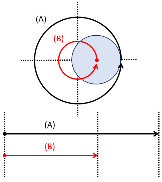
However, in the case of arc machining, the distance traveled between the center of the tool and the perimeter of the tool is different.
This means that the speed of movement between the center of the tool and the periphery of the tool when the tool makes one revolution is also different.

[In the case of arc movement] (A) Distance traveled around the perimeter of the tool (B) Distance traveled around the center of the tool
If arc cutting is performed with the feed rate reference value set to one direction, the actual feed around the tool will be higher than the specified value, and the risk of tool damage will increase.
Therefore, it compensates for the "F" on the program, which is the movement of the center of the tool, so that the tool circumference can move at the feed rate suitable for machining.
First, calculate the amount of travel around the tool (= machining diameter) and the ratio to the amount of travel in the center of the tool.
When helical machining φ18 holes with AE-VMSS φ10 carbide anti-vibration type end mill
(Machining diameter - tool diameter) ÷ machining diameter = (18-10) ÷ 18 = 0.444 ...
Multiply this by the rotation speed (2,240 min-1) and the feed amount per revolution (0.18375 mm/rev) obtained in (1).
2,240×0.18375×0.4444・・・≈183mm/min
This value is the corrected feed rate.
(3) Calculation of the distance traveled in the Z-axis direction per helical lap
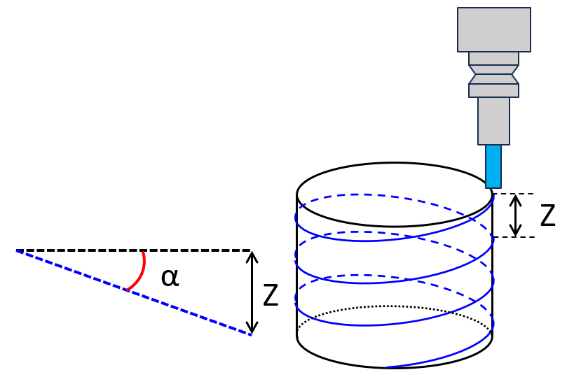
In helical machining, the command of the movement of the arc interpolation and the movement in the Z-axis direction work simultaneously.
Calculate how much inclination (ramping angle) the tool center will go down with respect to the distance it moves (radial direction only).

(α) Ramping angle (z) Z-axis travel distance
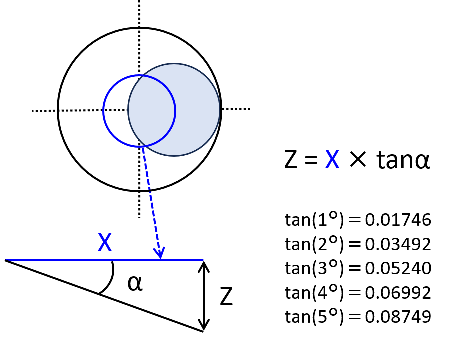
If the distance traveled by the center of the tool (radial direction only) is "X",
X = (Hole diameter to be machined - Tool diameter) ×3.14
When helical machining φ18 holes with AE-VMSS φ10
X=(18-10)×3.14=25.12(mm)
If the distance that the tool moves in the axial direction is "Z", then
Z=X×tan (ramping angle)
The general ramping angle is 2~3°.
Z=X×tan3°=25.12(mm)×0.05240=1.316(mm)

(α) Ramping angle (X) Distance traveled by the center of the tool (radial direction only) (z) Distance traveled in the Z-axis direction
The value of the tangent here is the percentage of the height at each angle when the base is 1.
The height (mm) can be calculated by multiplying the center of the tool (radial direction only) by the tangent value of that angle.
With the above, we have calculated the numbers of rotational speed (S), feed velocity (F), and distance (Z) to move in the Z-axis direction per helical movement.
In actual machining, make adjustments that take into account the runout of the tool and workpiece material, chip discharge, etc.